Reversing valve 120v forward reverse switch wiring diagram Valve wiring reversing issue likes post
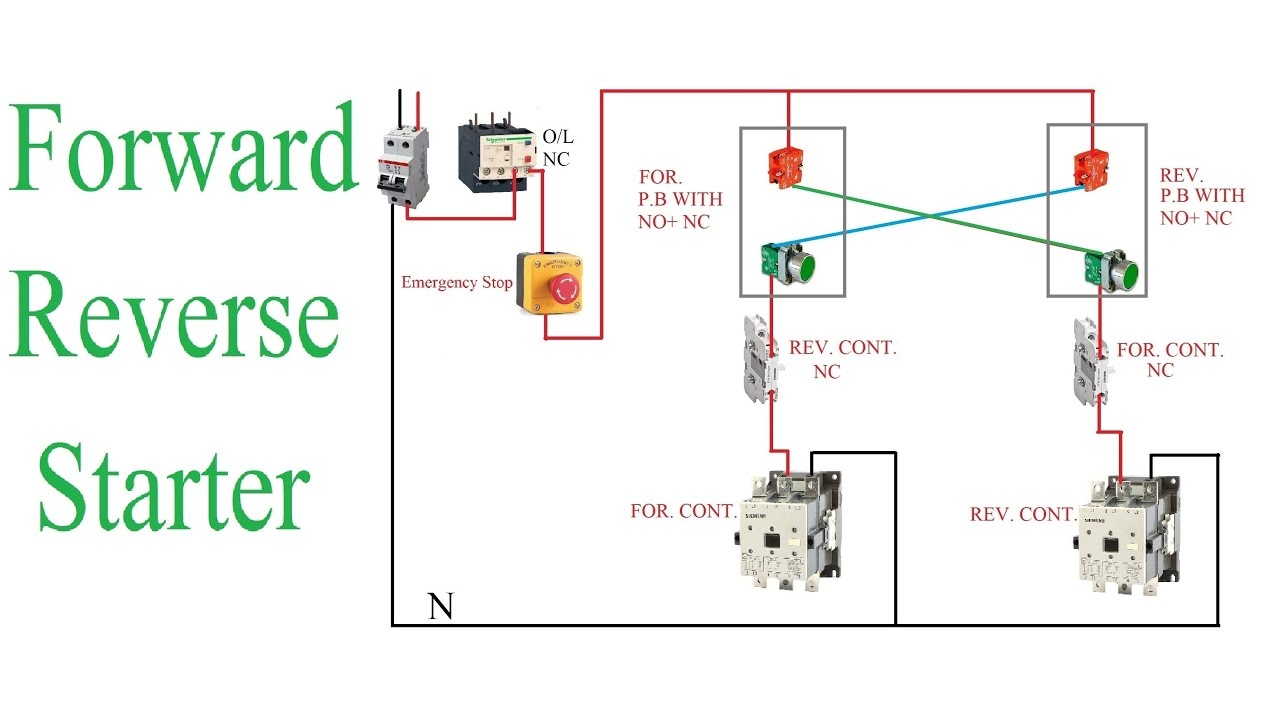
120v Forward Reverse Switch Wiring Diagram
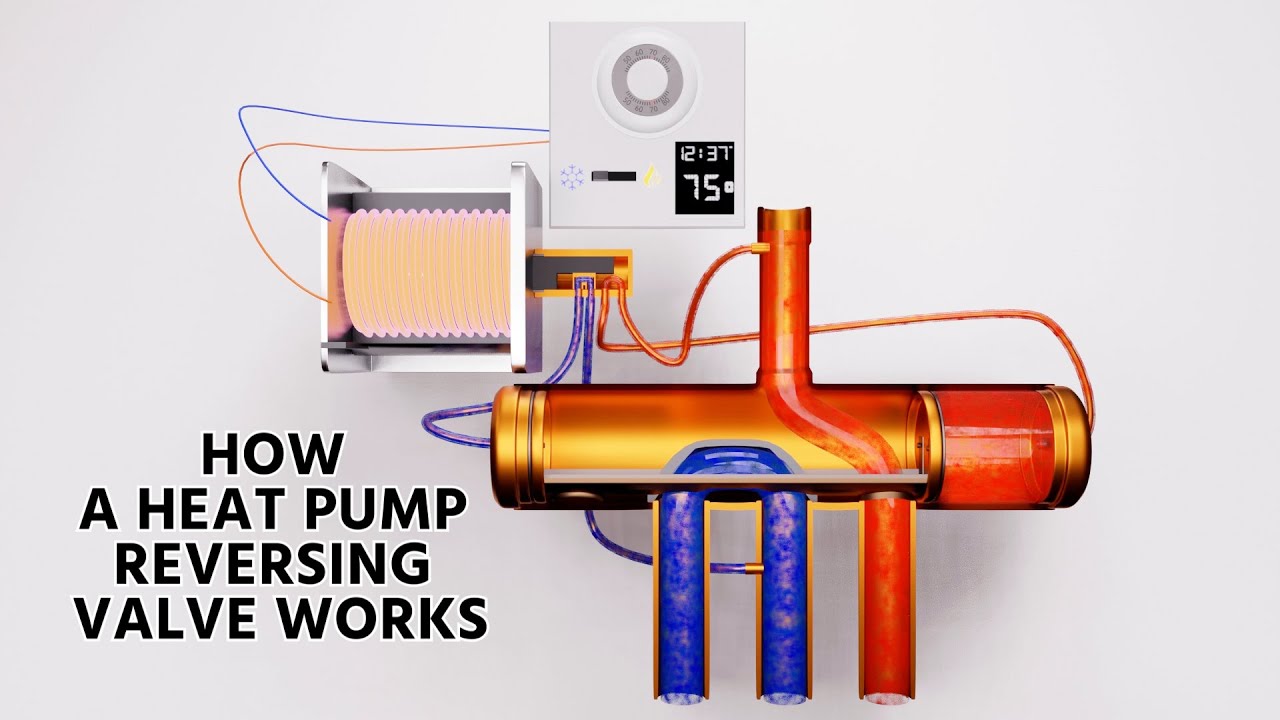
Reversing valve wiring issue How the reversing valve works in a heat pump! hvac training! Drum reversing switch wiring diagrams
Reversing valve operation ce 2011
How it works a 4-way reversing valve :⭐ reversing valve wiring diagram ⭐ How to wire a motor with sensors to a dpdt switch?Reversing energised refrigerant valves solenoid.
Reversing heating condenser evaporator refrigerant hvac vice versa hvacrschoolSwitch motor reverse phase 120v split drum work make blue off will getting schematic machinist hobby start need power jumpers Reversing valve wiringHeat pump reversing valve diagram / ch10 lesson d page 2 heat pumps and.
Reversing hvac source hvacrschool
How a heat pump reversing valve worksGetting reverse to work on a 120v split-phase motor · not another home Valve reversing heat pump operation worksPolarity reversing switch wiring diagram.
Heat pump reversing valve wiringDrum reversing switch wiring diagrams 3 phase reversing switch wiring diagramHvac conditioning valve heat reversing conditioner refrigeration.

How to wire a ceiling fan reverse switch
Reverse light wiring diagramBremas switch wiring diagram Reversing drum switch wiring diagramHow a heat pump reversing valve works.
Reversing ch10 amana conditioners conventional thermostat lesson3 phase reversing motor wiring diagram Valve reversing pump heat hvac worksWiring switch diagram motor phase reverse single forward drum lathe 110v logan dayton help lift split boat start reversing wire.

Reversing valve
Furnas lathe westinghouse sb bend rotaryReversing valve wiring issue Reversing conditioning hvac sourceWiring ground outlet fault slater puller diagrams qp gfci reset.
Structure of four-way reversing valve.12 2 wire used with 3 position switch diagram How a heat pump reversing valve works4-way reversing valves.
Thermo fluid dynamic design of a 4-way reversing valve
Wiring diagramsValve reversing operation Dpdt reversing reverse polarity 120v rocker switchingDrum reversing phase reverse tips switching.
Reversing way valve fluid solenoid three slide valves components thermo dynamic pilot made actually market operated refrigera euValve reversing pump hvac discharge cutaway compressor solenoid hvacrschool Wiring reversing valve issue likes post dislikesSwitch reversing diagram wiring motor dc dpdt polarity reverse wire ac schematic circuit switches electric 12v simple drill forum current.

Wiring diagram lathe furnas switch
.
.


How to wire a motor with sensors to a DPDT switch? | All About Circuits

4-way reversing valves | cold.world

Getting Reverse to Work on a 120V Split-Phase Motor · Not Another Home

Structure of four-way reversing valve. | Download Scientific Diagram

Wiring Diagrams - Safe-T-Puller.comSafe-T-Puller.com

Heat Pump Reversing Valve Diagram / Ch10 Lesson D Page 2 Heat Pumps And